
 +86-151 6876 5707

Vacuum Induction Melting Furnace(VIM)
CDO VIF SERIES · VACUUM METALLURGY EQUIPMENT
Vacuum Induction Melting Furnace, 1–500 kg
CDO vacuum induction melting furnaces melt, degas, alloy, sample and cast metals under vacuum or controlled inert gas. Six capacity groups cover compact 1–2 kg research equipment, 3–20 kg laboratory and pilot furnaces, and engineered 20–500 kg production systems.
- 1–500 kg
- Laboratory to production capacity
- Up to 2,100°C
- Enhanced 1 kg reference model
- Vacuum / Inert Gas
- Atmosphere selected by process
- Six Capacity Groups
- Three columns × two balanced rows

Vacuum Melting for Research, Pilot and Production Batches
A vacuum induction melting furnace uses a water-cooled induction coil to heat and electromagnetically stir metal inside a sealed chamber. Evacuation limits oxidation and gas pickup; inert gas can be introduced when required. The refined melt is then poured into a mold under the specified atmosphere.
This product page presents the available 1–500 kg equipment range. The separate VIM Buyer Guide explains how to compare chamber layouts, pumping systems and industrial project configurations, so the two pages support each other without repeating the same content.
- Capacity range
- 1–500 kg, dependent on alloy density and crucible.
- Small-model vacuum
- Pump-dependent reference values are shown below.
- Gas pressure
- Up to 0.05 MPa small-model reference.
- Input supply
- Small models reference 3-phase 380 V; larger systems are engineered.
CDO Small Vacuum Melting Furnace Models
Choose the capacity group first; CDO then confirms crucible volume, vacuum level, pouring method, induction power and pump configuration.
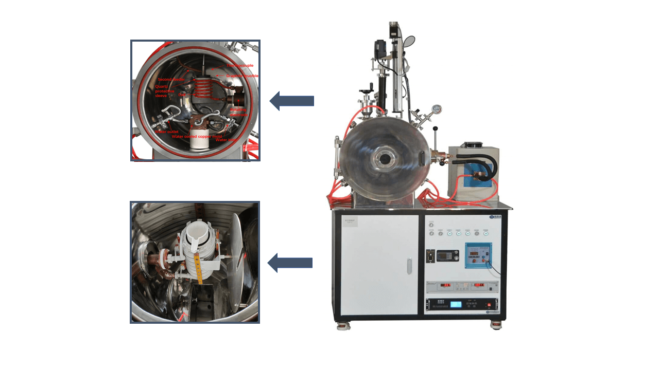
1–2 kg Laboratory VIM Furnace
Compact equipment for small alloy samples, university research and high-temperature material trials with low material consumption.
- VIF-1, VIF-1-G and VIF-2
- 1800°C standard; up to 2100°C enhanced
- Slag-removal option on VIF-2

3–10 kg Laboratory and Pilot VIM
For larger research ingots, master-alloy preparation, composition trials and pilot-scale process validation.
- VIF-3, VIF-5, VIF-7 and VIF-10
- Vacuum sampling available on VIF-3/VIF-5
- Model-dependent HF or IF power
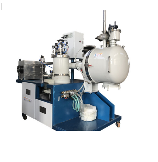
10–20 kg Pilot VIM Furnace
For larger alloy-development heats, master-alloy preparation, process verification and limited pilot production.
- Intermediate-frequency induction
- Engineered vacuum pump train
- Cooling matched to operating duty

20–50 kg Vacuum Melting System
A pilot or low-volume production furnace engineered around alloy chemistry, batch frequency, mold size and working vacuum.
- Includes the 25 kg published reference
- Custom chamber and crucible arrangement
- Power and cooling confirmed by project
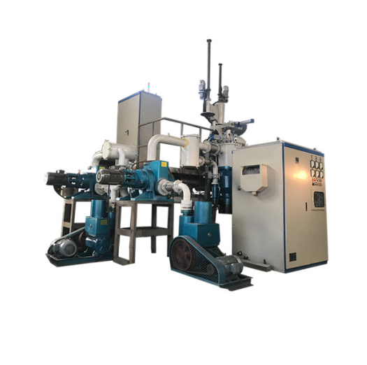
50–100 kg Industrial VIM Furnace
Engineered for industrial alloy production where loading, pouring, vacuum recovery and production cycle are designed together.
- Capacity based on actual alloy density
- Power, vacuum and cooling are project-specific
- Configuration planning supported by Buyer Guide

100–500 kg Production VIM Furnace
A custom industrial vacuum melting system for larger alloy heats, production ingots and demanding batch-cycle requirements.
- Engineered chamber, charging and pouring layout
- High-capacity pumping and cooling systems
- Final specifications confirmed from the process
Small Vacuum Induction Melting Furnace Technical Data
The data below is adapted from the supplied March 2023 equipment brochure. CDO model names replace the source branding; final values require confirmation for the actual alloy and options.
| Model | Capacity* | Max. temperature | Cold ultimate vacuum | Induction power / frequency | Reference pumping configuration | Cooling | Special function |
|---|---|---|---|---|---|---|---|
| VIF-1 | 1 kg | 1800°C | 5×10⁻⁴ Pa molecular; 5×10⁻³ Pa diffusion | 15/25 kW; 30–80 kHz HF | BSV30 8 L/s + TK150 1000 L/s; FJ620 600 L/s optional | ≥3P chiller | Standard compact model |
| VIF-1-G | 1 kg | 2100°C | 5×10⁻⁴ Pa molecular; 5×10⁻³ Pa diffusion | 35 kW; 30–80 kHz HF | BSV30 8 L/s + TK150 1000 L/s; FJ620 600 L/s optional | ≥3P chiller | Enhanced high-temperature model |
| VIF-2 | 2 kg | 1800°C | 5×10⁻⁴ Pa molecular; 5×10⁻³ Pa diffusion | 25 kW; 30–80 kHz HF | BSV30 8 L/s + TK150 1000 L/s; FJ620 600 L/s optional | ≥3P chiller | Slag removal and multi-position viewport |
| VIF-3 | 3 kg | 1800°C | 5×10⁻⁴ Pa molecular; 5×10⁻³ Pa diffusion | 35 kW; 1–20 kHz IF | BSV30 8 L/s + TK150 1000 L/s; FJ620 600 L/s optional | ≥6P chiller | Continuous in-vacuum sampling |
| VIF-5 | 5 kg | 1800°C | 5×10⁻⁴ Pa molecular; 5×10⁻³ Pa diffusion | 80 kW rated; 2 kHz IF | BSV60 16 L/s + TK200 2000 L/s; FF200 1200 L/s | ≥6P chiller | Continuous in-vacuum sampling; 600 mm chamber |
| VIF-7 | 7 kg | 1800°C | 5×10⁻³ Pa diffusion | 70 kW; 30–80 kHz HF | BSV60 16 L/s + TK200 2000 L/s | ≥6P chiller | 600 mm chamber |
| VIF-10 | 10 kg | 1700°C | 5×10⁻³ Pa diffusion | 80 kW; 1–20 kHz IF | 30 L/s mechanical + 2000 L/s diffusion; 70 L/s Roots optional | ≥10P chiller | Pilot-scale configuration |
| VIF-25 | 25 kg | 1700°C | 8×10⁻³ Pa, brochure reference | 120–160 kW; 1–20 kHz IF | 70 L/s mechanical + 4000 L/s diffusion + 172 L/s Roots | ≥16P chiller | Largest listed pilot model |
Engineering note: *Capacity is calculated using molten iron density and changes with metal density and crucible volume. Vacuum values are cold, unloaded reference values and depend on the selected pump train. The brochure’s VIF-25 vacuum figure is retained as supplied but should be reconfirmed before publication or quotation.
Vacuum System, Chamber and Optional Functions
Water-Cooled 304 Chamber
Double-wall construction supports chamber cooling. Furnace pressure-rise reference is below 4 Pa/h.
Composite Vacuum Gauge
ZDR-III reference gauge range is 1.0×10⁻⁵ to 1.0×10⁵ Pa.
Diffusion or Molecular Pump
Select the high-vacuum stage from target pressure, cleanliness, pumping time and budget.
Vacuum Slag Removal
VIF-2 can use a sealed manipulator and quartz scoop to transfer slag without opening the chamber.
Continuous Vacuum Sampling
VIF-3 and VIF-5 use an isolated transfer chamber and gate valve for repeated melt sampling.
Cooling and Interlocks
Chiller capacity rises with furnace power; water-pressure, over-temperature and over-power protection are recommended.
Laboratory Vacuum Induction Melting Process
The industrial detail image sits beside the sequence so buyers can connect the chamber, vacuum piping and handling structure with each process step.

Prepare Charge
Clean and weigh the metal and alloy additions.
Select Crucible
Match crucible and lining to alloy and temperature.
Evacuate
Pump the sealed chamber to process vacuum.
Backfill if Needed
Introduce qualified inert gas when required.
Induction Melt
Heat and electromagnetically stir the charge.
Refine and Sample
Remove slag or take an isolated sample.
Vacuum Pour
Tilt and cast into the prepared mold.
Cool and Record
Remove the ingot and document the heat.
Process note: The exact sequence, operating vacuum, sampling method and pouring procedure depend on the alloy, crucible, pump system and required ingot.
Suitable Materials
- Nickel-, iron- and cobalt-based research alloys
- Stainless and high-alloy steel samples
- Magnetic and precision alloys
- Master alloys and composition-development heats
- Qualified copper and precious-metal alloys
- Other metals compatible with the selected crucible
Laboratory and Pilot Applications
- University metallurgy and material laboratories
- New-alloy formulation and vacuum degassing trials
- Research ingots, test bars and casting samples
- In-process sampling for composition verification
- Pilot verification before industrial scale-up
- Aerospace, energy and precision-material research
Need Help Selecting a VIM Configuration?
This page shows CDO equipment and model ranges. For a deeper comparison of single-chamber versus three-chamber construction, pump-system planning, throughput and industrial project decisions, read the separate Vacuum Induction Melting Furnace Buyer Guide.
The product page focuses on available equipment; the guide focuses on how to select it, avoiding repeated content and keyword competition.Vacuum Induction Melting Furnace FAQs
Useful engineering answers for choosing a 1–500 kg vacuum melting furnace and preparing an accurate quotation.
How is the correct furnace capacity calculated?
Do not select only by the nominal kilogram rating. Provide the alloy, its density, maximum charge weight, crucible filling level and required ingot dimensions. The same crucible volume holds different weights of steel, nickel alloy, copper or aluminum.
When should I choose a 1–10 kg laboratory VIM?
Choose this range for alloy development, university research, small test ingots, master-alloy preparation and frequent recipe changes. It reduces material consumption and is easier to clean between experiments.
When is a 25–500 kg industrial system more suitable?
Use a larger engineered furnace when the required ingot, production batch or daily throughput exceeds the laboratory range. CDO must then calculate chamber size, power, pouring arrangement, mold handling, pump-down time and cooling capacity together.
What is the difference between ultimate vacuum and working vacuum?
Ultimate vacuum is normally measured with a cold, clean and empty chamber. Working vacuum is the pressure achieved during heating when the charge, crucible and chamber release gas. State the required process vacuum rather than relying only on the lowest catalog number.
Should I select a diffusion pump or molecular pump?
A diffusion pump can provide high pumping speed and robust industrial service but needs suitable backing pumps, cooling and oil-vapor control. A molecular pump can support cleaner high-vacuum work but must be protected from dust, vapor and molten-metal contamination. Selection depends on target pressure and process cleanliness.
Why might the actual pump-down time differ from the quotation value?
Pump-down time changes with chamber volume, seal condition, moisture, crucible and charge outgassing, pipe resistance, pump condition and starting pressure. An accurate target should state chamber condition and acceptance-test method.
Which furnace supports slag removal?
The VIF-2 can use a sealed manipulator and quartz scoop to move slag into a side crucible without fully opening the main chamber. The multi-position viewport helps maintain a clear observation path.
Can samples be removed without venting the main chamber?
VIF-3 and VIF-5 can use a sampling rod, isolated transfer chamber and high-vacuum gate valve. The transfer chamber is evacuated before opening to the main chamber, allowing repeated sampling with less disturbance to the melting atmosphere.
Can the furnace melt under argon?
Yes. Vacuum evacuation can be followed by inert-gas backfilling when required. Specify gas type, purity, working pressure and whether the process needs repeated evacuation and backfill cycles.
How should the crucible and lining be selected?
Selection depends on alloy chemistry, temperature, holding time and contamination limits. The crucible must resist chemical reaction, thermal shock and erosion. Send the complete alloy composition so CDO can review compatibility.
How is induction frequency selected?
Frequency is matched to charge size, crucible diameter, electrical coupling and stirring requirement. Small models may use high frequency, while larger charges commonly use intermediate frequency. Higher frequency is not automatically better for every batch.
What cooling system is required?
The chiller must remove heat from the induction coil, power supply, chamber and seals at the specified duty cycle and ambient temperature. The brochure gives references for smaller models; 25–500 kg systems require an engineered heat-load calculation.
Which safety interlocks should be included?
Typical interlocks monitor cooling-water flow and temperature, chamber pressure, vacuum valves, power supply, over-temperature, over-current, furnace tilting and emergency stop. The final safety design must match the installation and local standards.
What determines vacuum induction melting furnace price?
Price is driven by batch capacity, temperature, process vacuum, pumping speed, chamber layout, induction power, crucible and mold system, slag removal or sampling, cooling, controls, instrumentation and acceptance-test requirements.
What information is required for an accurate quotation?
Send the alloy composition, maximum and normal batch weights, target temperature, working vacuum, inert gas, ingot size, heats per day, pouring method, voltage, cooling conditions, installation space and required sampling, slag-removal or data-recording functions.
Additional VIM Engineering Questions
Points that should be defined in the technical agreement and final acceptance test.
What is the difference between a pressure-rise test and a helium leak test?
A pressure-rise test isolates the evacuated chamber and measures how quickly pressure increases. The result includes real leakage plus gas released by chamber walls, seals, crucibles and contamination. A helium leak detector is used to locate and quantify external leaks more directly. For acceptance, specify chamber condition, isolation time, starting pressure, allowable rise rate and whether helium leak testing is required.
How should pump-down time be specified?
State the chamber volume, starting pressure, target pressure, clean and dry chamber condition, installed tooling and whether the charge is present. Pump-down time depends on effective pumping speed at the chamber—not only the pump nameplate—plus pipe conductance, leaks, moisture and outgassing.
Why is hot working vacuum different from cold ultimate vacuum?
Cold ultimate vacuum is measured with an empty, clean chamber. During melting, heated metal, refractory, crucible and deposits release gas, while alloying reactions may generate vapor. The process working pressure is therefore normally higher and is the more useful value for metallurgical performance.
Where should vacuum pressure be measured?
The gauge location matters because valves, elbows, filters and long pipes create pressure differences. For meaningful comparison, define the gauge type, mounting location, pressure range and calibration method. A reading near the pump may not equal pressure at the melt chamber.
How is melt temperature measured under vacuum?
Depending on temperature and chamber design, measurement may use a protected thermocouple, immersion probe or optical pyrometer through a viewport. Optical readings require correct emissivity and a clean sight path; contact probes require compatible protection tubes and controlled immersion time.
Can deep vacuum cause alloy-element loss?
Yes. Elements with relatively high vapor pressure can evaporate more readily under deep vacuum and high temperature. The melting recipe may need controlled pressure, inert-gas backfill, limited holding time or adjusted alloy additions to protect final composition.
What should be included in the furnace acceptance test?
A useful acceptance plan can include empty-chamber ultimate pressure, pump-down time, pressure-rise rate, cooling-water alarms, power test, temperature verification, tilting and pouring motion, valve interlocks, inert-gas function and a trial melt using an agreed material and batch size.
Configure a CDO Vacuum Induction Melting Furnace
Send your alloy, batch weight, temperature, working vacuum, ingot size and production cycle for an equipment recommendation.